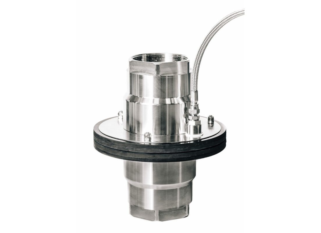
Powered Emergency Release Coupling (PERC)
Highest safety level, three ways of release
- Release by ESD-signal.
- Release by manual override, independent of electrical signal.
- Reverting from nitrogen activated to passive breaking pin. Breaking pins designed to be the weakest point of hose or manifold.
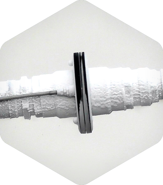
Ability to actively and remotely release the coupling without strain on the transfer system.
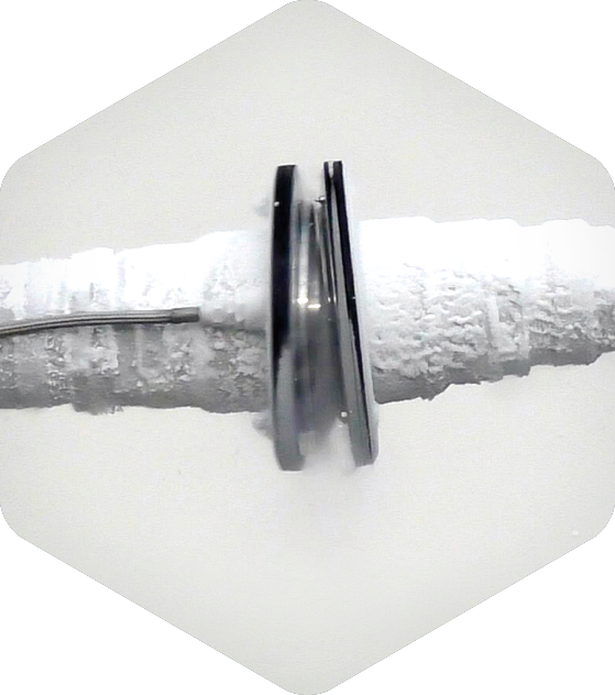
An active safety device but in the event of a ‘Black out’ has the back up of becoming a passive Break Away Coupling.
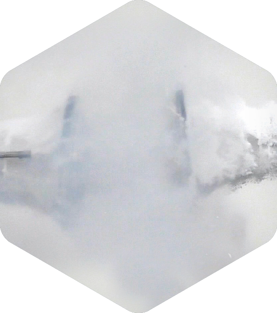
Designed to protect the manifolds in any situation.
PERC control unit HPN2 – SIL2
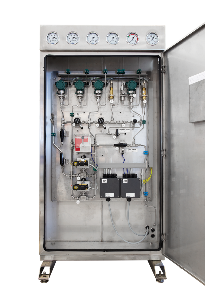
Area of use
- The dedicated release and monitoring system for the MannTek PERC coupling.
- It includes the complete control, monitoring and release system, which uses high pressure Nitrogen in the release mechanism. The system also features a pilot pressure regulator to constantly monitor the system and keep it free from moisture and ice.
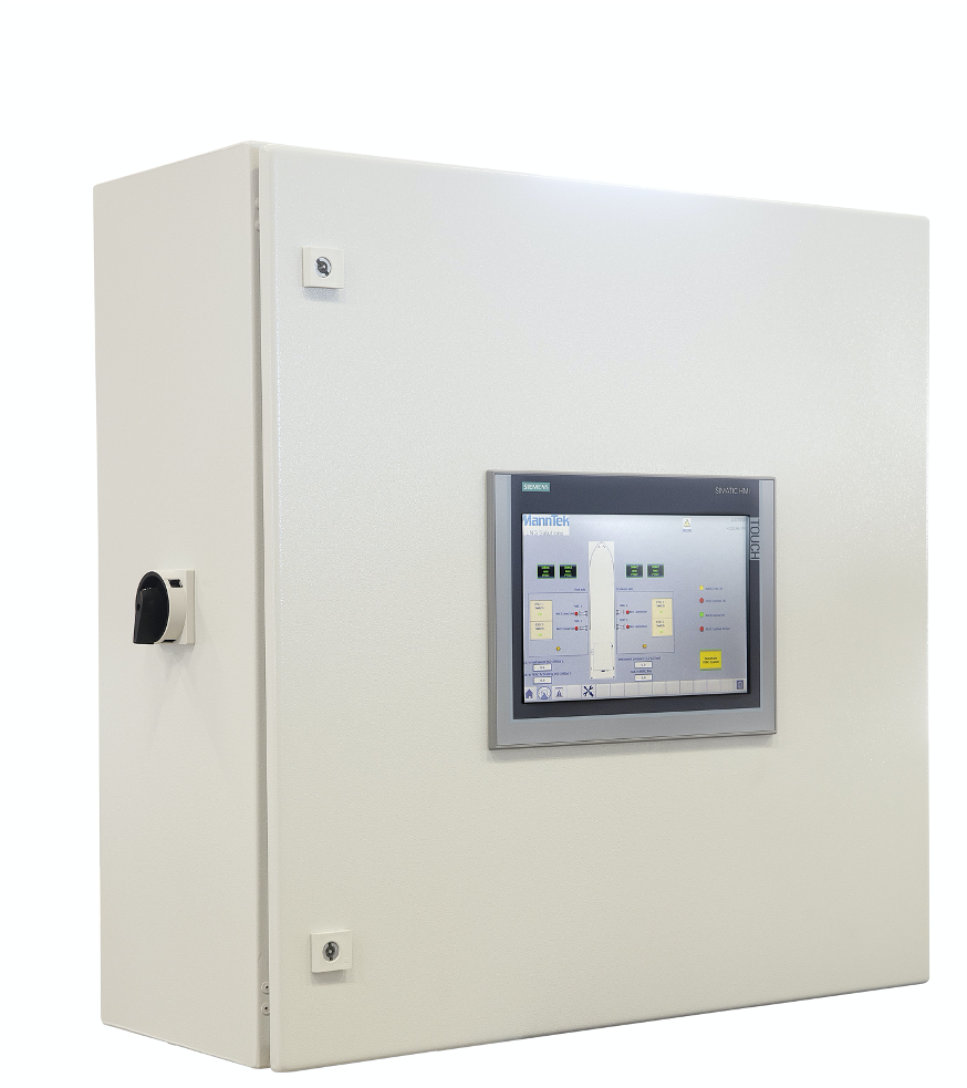
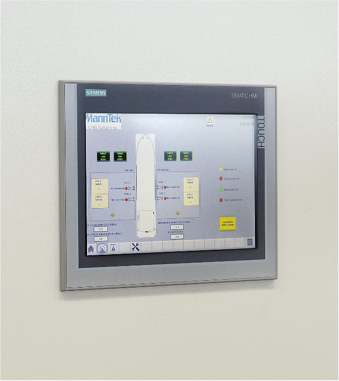
PLC – monitoring and control unit
- The software is programmed under the supervision of a third party.
- Programmed uniquely for each application.
- Monitors the system during the whole bunkering/transfer operation.
- Eliminates the human factor and ensures all steps in the periodical test are carried out.
PLC control with SIL2 compliance
- MannTek SIL2 PLC LNG transfer systems have been assessed by DNV-GL and declared compliant to SIL2. This extra safety feature has been developed in accordance with IEC 61508 and IEC 61511 with input data from the PDS Data Handbook 2010.
- Identifying mean time between failure (MTBF), probability of failure on demand (PDF), all safety instrumented functions (SIF) and achieving a minimum probability of failure on demand is compliant with safety integrity level SIL2.
- The SIL2 compliance is on the whole LNG Transfer System and includes: PERC, DCC, HPN2 PLC control system, ESD1&2 functionality, the logic solver i.e. Siemens PLC controller and software, sensor elements and final elements.

Benefits
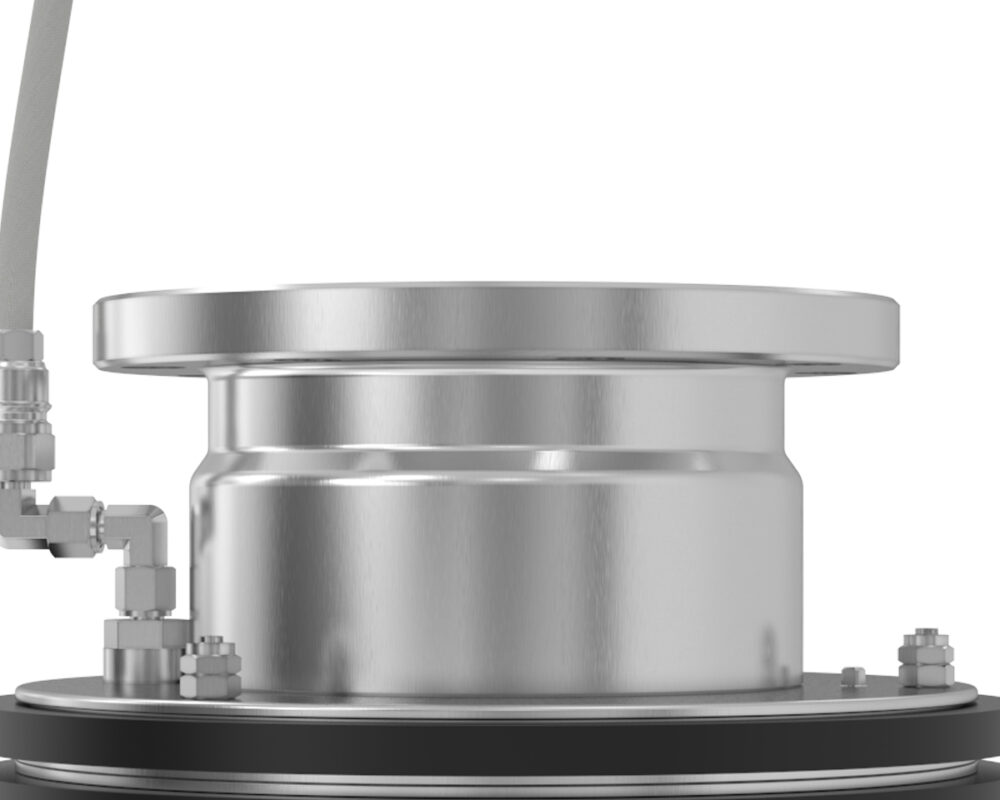
no nipples or reducers
No nipples or reducers necessary - produced with a wide range of flanges and threads.
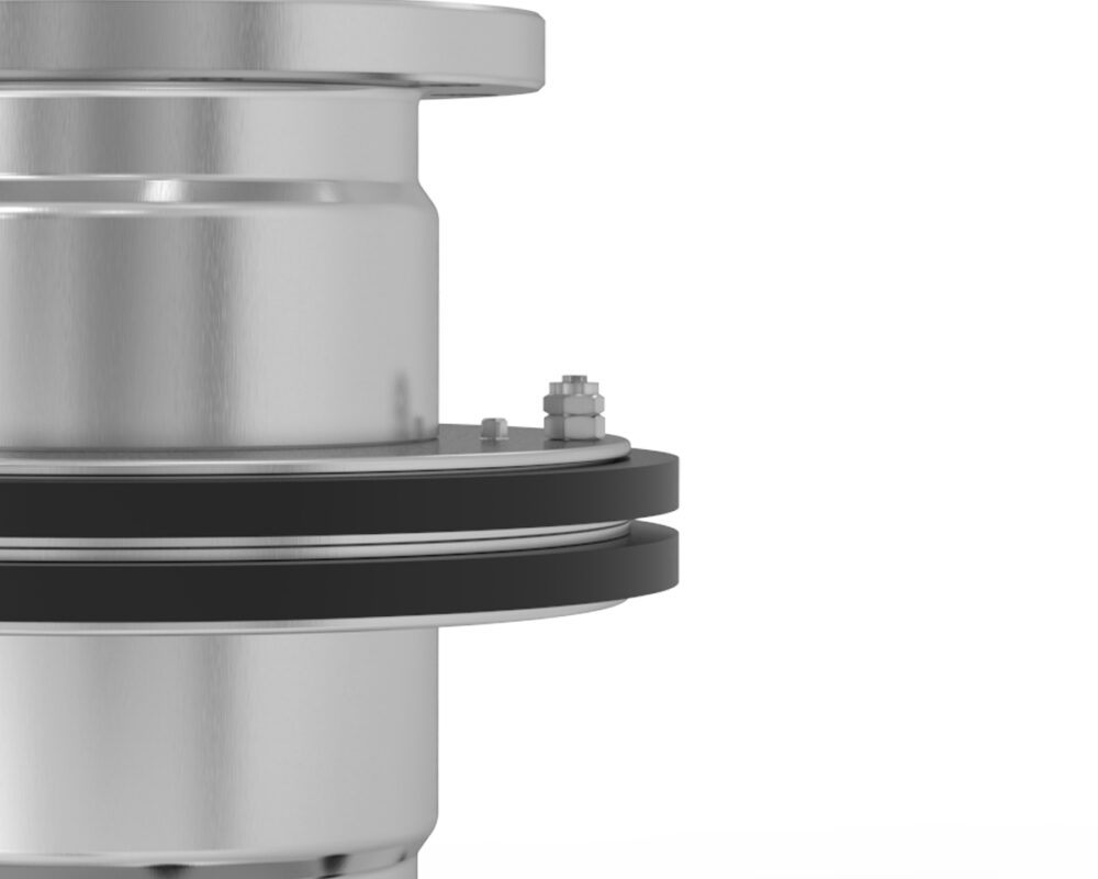
dedicated
The dedicated nitrogen chamber protects the valve mechanism from dirt and moisture.
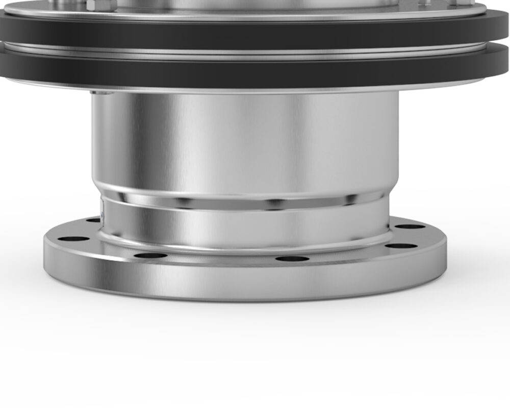
activiation
After activation the unit can be reset in minutes without special tools.
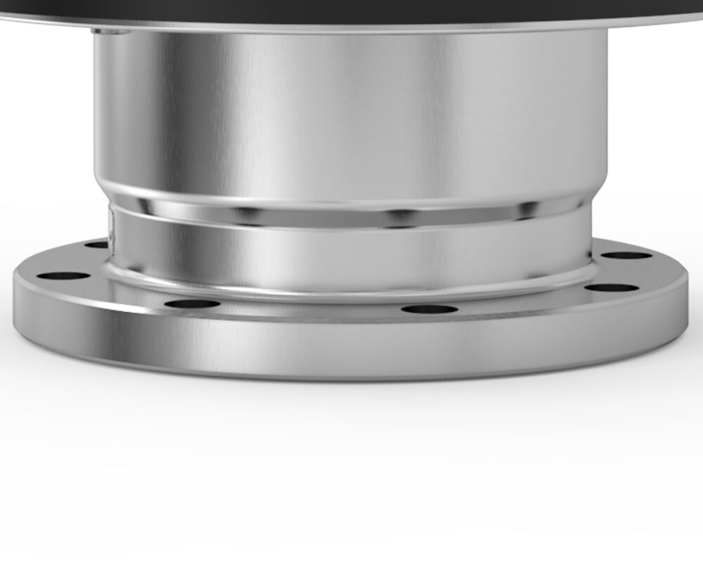
inlet and outlet
Choose inlet and outlet connections individually - any combinations of connections available.
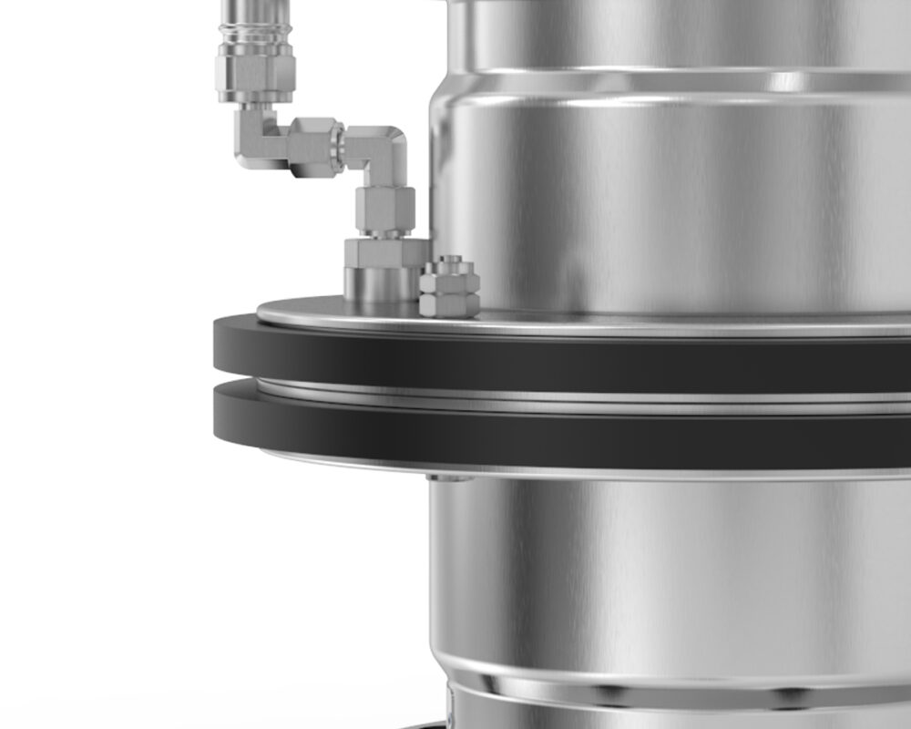
release
Release function is integrated in the PERC design - the most lightweight and compact.
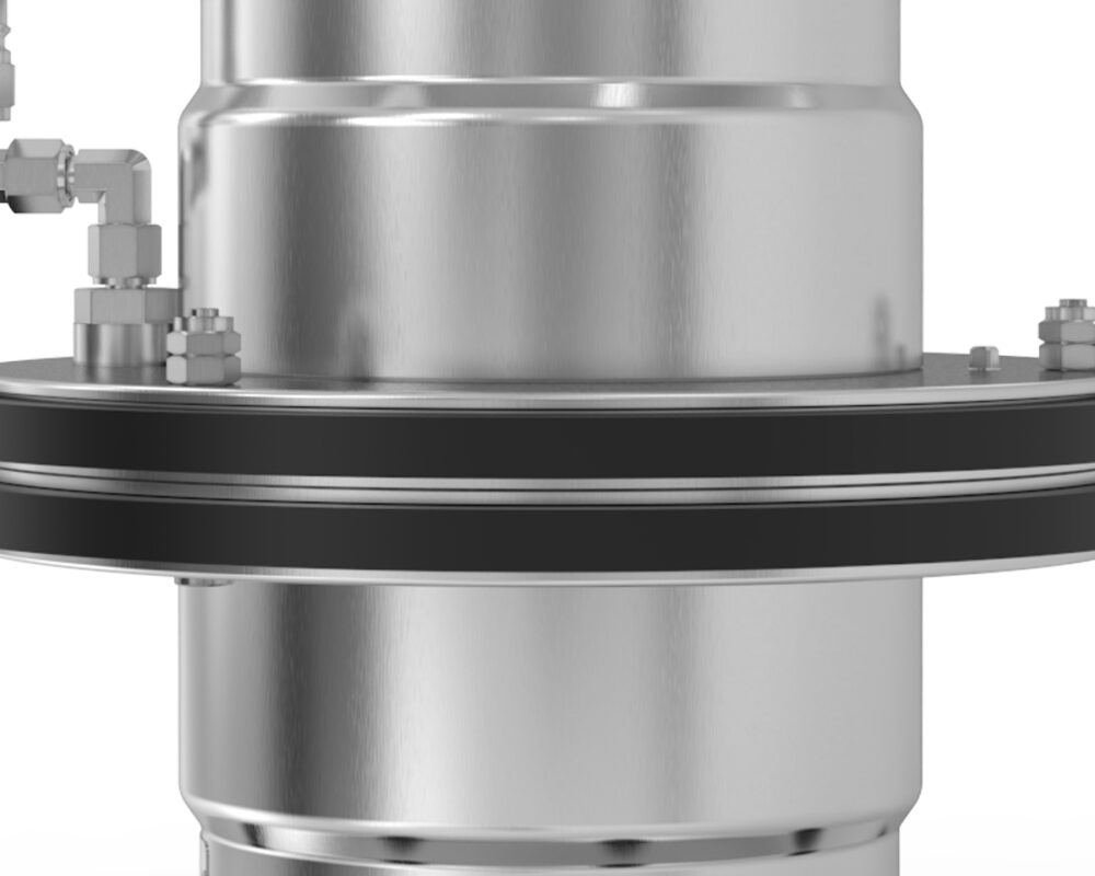
reliable
Reliable poppet valve design.
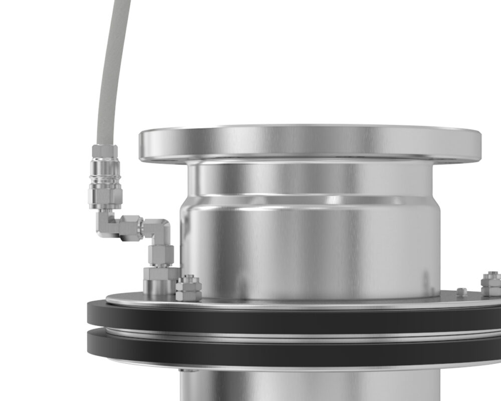
variation
Variation of breaking load - will be calculated for each installation.
Technical data
| Treaded connections | Flanged connections | Flow rate | Materials | Seals | |
|---|---|---|---|---|---|
| 2½” (DN65) | Female or male NPT thread | EN/ANSI/TW/TTMA | Up to 2.800 L/min | Specified in configurator | PTFE |
| 3” (DN80) | Female or male NPT thread | EN/ANSI/TW/TTMA | Up to 3.850 L/min | Specified in configurator | PTFE |
| 4” (DN100) | Female or male NPT thread | EN/ANSI/TW/TTMA | Up to 6.500 L/min | Specified in configurator | PTFE |
| 6” (DN150) | Female or male NPT thread | EN/ANSI/TW/TTMA | Up to 14.400 L/min | Specified in configurator | PTFE |
| 8” (DN200) | Female or male NPT thread | EN/ANSI/TW/TTMA | Up to 24.200 L/min | Specified in configurator | PTFE |
Service
FAT PERC System
Case
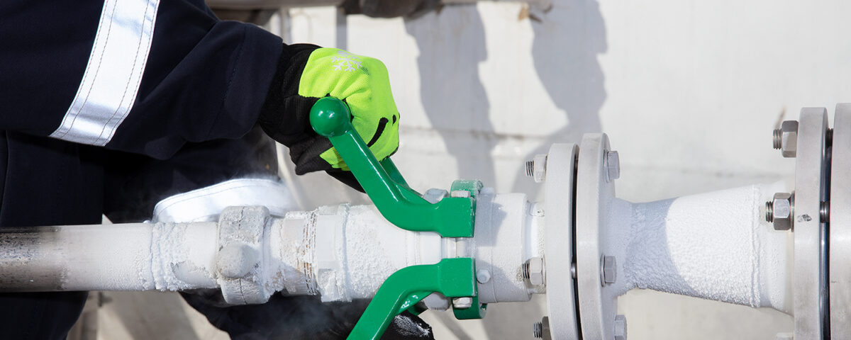
MS Coralius
MS Coralius was supplied with a LNG Transfer System. The LNG Transfer System supplied to…
Read more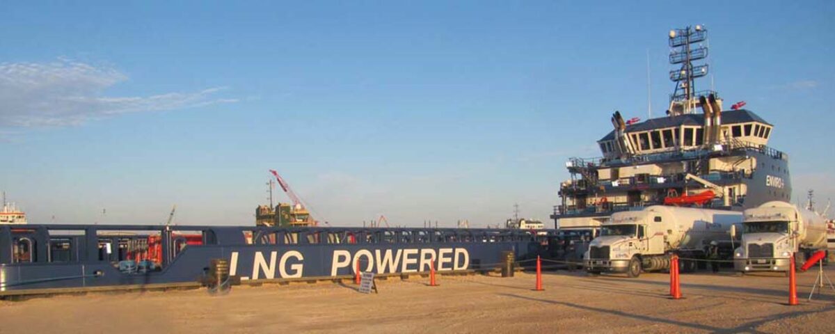
Harvey energy
US first LNG powered OSV. The 3” DCC couplings in use for bunkering Harvey Energy.…
Read more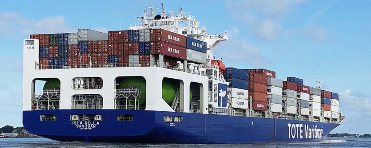
Tote Maritime
Jacksonville, Florida, January 9 2016, the world’s first LNG propelled containership bunkered LNG for the…
Read more